
Table of Contents
ToggleParallel Operation of Shunt Generator
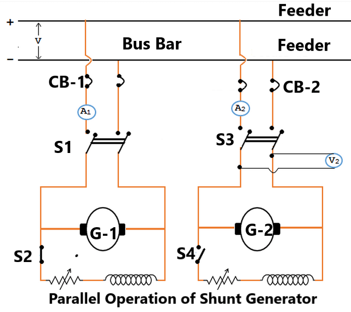
The generators in a power plant are connected in parallel through bus-bars. The bus-bars are heavy thick copper bars and they act as +ve and -ve terminals. The positive terminals of the generators are connected to the +ve side of bus-bars and negative terminals to the negative side of bus-bars.
Fig. shows shunt generator 1 connected to the bus-bars and supplying load. When the load on the power plant increases beyond the capacity of this generator, the second shunt generator 2 is connected in parallel with the first to meet the increased load demand.
The procedure for paralleling generator-2 with generator-1 is as under:
The prime mover of generator 2 is brought up to the rated speed. Now switch S4 in the field circuit of the generator 2 is closed.
Next circuit breaker CB-2 is closed and the excitation of generator 2 is adjusted till it generates a voltage equal to the bus-bars voltage. This is indicated by voltmeter V2.
Now the generator 2 is ready to be paralleled with generator 1. The main switch S3 is closed, thus putting generator 2 in parallel with generator 1. Note that generator 2 is not supplying any load because it’s generated e.m.f. is equal to bus-bars voltage. The generator is said to be “floating” (i.e., not supplying any load) on the bus-bars.
If generator 2 is to deliver any current, then it’s generated voltage E should be greater than the busbars voltage V. In that case, the current supplied by it is I = (E – V)/Ra where Ra is the resistance of the armature circuit. By increasing the field current (and hence induced e.m.f. E), the generator 2 can be made to supply the proper amount of load.
The load may be shifted from one shunt generator to another merely by adjusting the field excitation. Thus if generator 1 is to be shut down, the whole load can be shifted onto generator 2 provided it has the capacity to supply that load. In that case, reduce the current supplied by generator 1 to zero (This will be indicated by ammeter A1) open C.B.-1 and then open the main switch S1.
Load Sharing of two generators
The load sharing between shunt generators in parallel can be easily regulated because of their drooping characteristics. The load may be shifted from one generator to another merely by adjusting the field excitation. Let us discuss the load sharing of two generators which have unequal no-load voltages.
Let E1, E2 = no-load voltages of the two generators
R1, R2 = their armature resistances
V = common terminal voltage (Bus-bars voltage)
then I1 = (E1 – V)/R1 and I2= (E2-V)/R2
Thus the current output of the generators depends upon the values of E1 and E3.These values may be changed by field rheostats. The common terminal voltage (or bus-bars voltage) will depend upon
(i)the e.m.f.s of individual generators and (ii) the total load current supplied.
It is generally desired to keep the bus bars voltage constant. This can be achieved by adjusting the field excitations of the generators operating in parallel.
Parallel Operation of Compound Generators
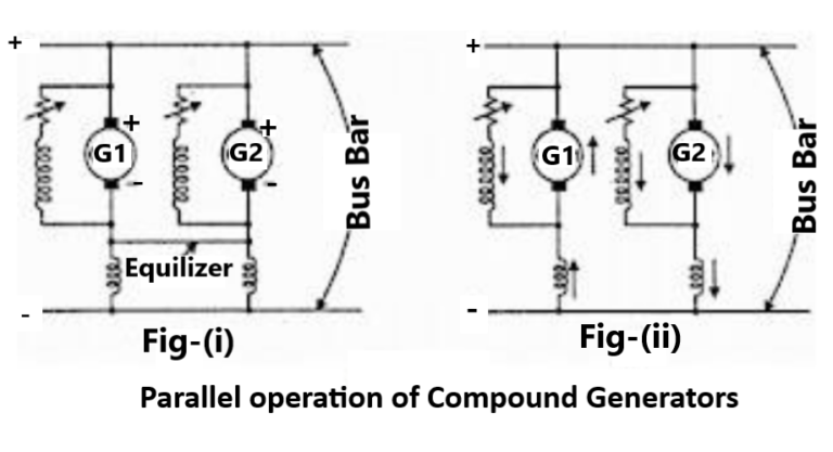
Under-compounded generators also operate satisfactorily in parallel but over compounded generators will not operate satisfactorily unless their series fields are paralleled. This is achieved by connecting two negative brushes together as shown in Fig.(i). The conductor used to connect these brushes is generally called equaliser bar. Suppose that an attempt is made to operate the two generators in Fig.(ii) in parallel without an equalizer bar. If, for any reason, the current supplied by generator 1 increases slightly, the current in its series field will increase and raise the generated voltage.
This will cause generator 1 to take more load. Since total load supplied to the system is constant, the current in generator 2 must decrease and as a result, its series field is weakened. Since this effect is cumulative, the generator 1 will take the entire load and drive generator 2 as a motor. Under such conditions, the current in the two machines will be in the direction shown in Fig.(ii). After machine 2 changes from a generator to a motor, the current in the shunt field will remain in the same direction, but the current in the armature and series field will reverse.
Thus the magnetising action, of the series field opposes that of the shunt field. As the current taken by the machine 2 increases, the demagnetizing action of series field becomes greater and the resultant field becomes weaker. The resultant field will finally become zero and at that time machine 2 will short circuit machine 1, opening the breaker of either or both machines.
When the equalizer bar is used, a stabilizing action existsAnd neither machine tends to take the entire load. To consider this, suppose that current delivered by generator 1 increase. The increased current will not only pass through the series field of generator 1 but also through the equalizer bar and series field of generator 2.Therefore, the voltage of both the machines increases and the generator 2 will take a part of the load.
Parallel operation of dc series generator
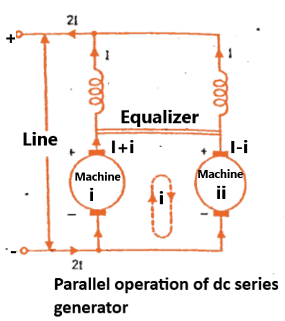
The interesting thing about the parallel operation of DC series generator is that DC series generators are not usually employed for supply of power. Instead DC series motors are arranged in parallel to operate as DC series generators during Electric Braking.
Series generators are rarely used in industry for supplying loads. Some applications like electric braking may employ them and operate two or more series generates in parallel.
The excitation of the machine I increase, increasing the load current delivered. As the total current is I the current supplied by machine II reduces, so also its excitation and induced emf.
Thus machine I takes greater and greater fraction of the load current with machine II shedding its load. Ultimately the current of machine II becomes negative and it also loads the first machine.
Virtually there is a short circuit of the two sources, the whole process is thus highly unstable. One remedy is for a problem as this is to make the two fields immune to the circulating current between the machines.
With the equalizer present, a momentary disturbance does not put the two machines out of action.
A tendency to supply a larger current by a machine strengthens the field of the next machine and increases its induced emf . This brings in stable conditions for operation rapidly.
Use of Equalizer Bars
Here comes the use of equalizer bars in the parallel operation of DC series generators. The possibility of reversal of either machine can be prevented by preventing the flow of circulating current produced due to inequalities of induced emfs of the machines through the series field winding.
This Aim can be achieved by connecting a heavy copper bar of negligible resistance across the two machines as shown in the figure.
Now the circulating current does not affect the field winding, but it get confined to the armature and the equalizing bars.
Now if the armature current increases, the terminal voltage drop occurs and the original condition is restored.
Cross connection of Field windings
If the field coils are cross-connected when the series motors are connected in parallel, then any increase in the current of the armature of generator 1, the increased current flows occurs through the field coil of generator 2. This increases the electromotive force of generator, which opposes the change in load sharing trying to stabilize the operation of the two generators at the original operating condition itself. Thus it will give more positive and better operation than equalizer connection.
Why DC Generator Parallel operated?
In a DC power plant, power is usually supplied from several generators of small ratings connected in parallel instead of from one large generator. This is due to the following reasons:
(i) Continuity of service
If a single large generator is used in the power plant, then in case of its breakdown, the whole plant will be shut down. However, if power is supplied from a number of small units operating in parallel, then in case of failure of one unit, the continuity of supply can be maintained by other healthy units.
(ii) Efficiency
Generators run most efficiently when loaded to their rated capacity. Electric power costs less per kWh when the generator producing it is efficiently loaded. Therefore, when load demand on power plant decreases, one or more generators can be shut down and the remaining units can be efficiently loaded.
(iii) Maintenance and repair
Generators generally require routine-maintenance and repair. Therefore, if generators are operated in parallel, the routine or emergency operations can be performed by isolating the affected generator while the load is being supplied by other units. This leads to both safety and economy.
(iv) Increasing plant capacity
In the modern world of increasing population, the use of electricity is continuously increasing. When added capacity is required, the new unit can be simply paralleled with the old units. In many situations, a single unit of desired large capacity may not be available. In that case, a number of smaller units can be operated in parallel to meet the load requirement. Generally, a single large unit is more expensive.
(v) Non-availability of single large unit
In many situations, a single unit of desired large capacity may not be available. In that case, a number of smaller units can be operated in parallel to meet the load requirement. Generally, a single large unit is more expensive.