
Parallel operation of DC link with AC network
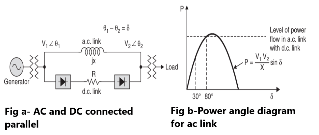
In case of a DC link the power to be transmitted depends upon the four control parameters Vr, V , α and β, all of which can be controlled more or less independently over a desired range. Thus when a d.c. system is operated in parallel with an a.c. system (Fig. ) following objectives can be achieved:
(a) Constant current flow.
(b) Constant power flow.
(c) Constant angle between the a.c. bus bar voltages.
(d) Constant voltage at either end
Control at Constant angle between the a.c. bus bar voltages helps in improving transient stability of the system. Better utilisation of the a.c. transmission lines can result. It is known that in case of a.c. lines power transmitted is given by the expression:
where V1, V2 are the voltages at the two ends of the line, X the inductive reactance and δ is the phase angle between V1 and V2. Usually a.c. lines are operated at an angle δ of about 30° in order to allow a margin for additional power flow which is sufficient to meet transient fluctuation in the load or to meet sudden changes in system conditions such as shunt faults.
However, if the a.c. system is connected to a d.c. link, the a.c. line can be operated at a much greater angle say 78–80° [Fig. (b)] which represents an increase of 95% in the transmission capacity of the line. In order to achieve this increase in power transmission it would be necessary for d.c. link to be controlled either by a signal proportional to δ or by measurement of the a.c. power flow.
In both cases a signal proportional to rate of change of the controlling parameter will be required to achieve good stabilised flow on the d.c. link. Under normal operating condition, the power flow through d.c. link would be small and hence the grid angle α, of the rectifier large so that when required during abnormal condition such as a shunt fault or a sudden increase in load, when power transmission through a.c. line decreases, the power flow can be opened up very quickly by decreasing the grid control angle to a suitable value. Facilities would also be necessary for reversal of power flow in the link due to sudden drop in the sending end voltage, particularly if these are due to a.c. system faults.
In order to meet objective Constant voltage at either end listed above it is desirable to use synchronous capacitors or/and Static Capacitor rather than use a d.c. link for the purpose. Voltage control may, however, be a fringe benefit from a d.c. link installed for other purposes, especially if the compensating equipment installed with the link can be controlled to maintain system voltage.