
Table of Contents
ToggleWhy Voltage control need in Power system?
A power system is said to be well designed if it gives a good quality of reliable supply. By good quality is meant the voltage levels within the reasonable limits. Practically all the equipment on the power systems are designed to operate satisfactorily only when the voltage levels on the system correspond to their rated voltages or at the most the variations are within say 5%.
If the voltage variation is more than a prespecified value, the performance of the equipment suffers and the life of most of the equipment also is sacrificed. The picture on a television set starts rolling if the voltage is below a certain level, the fluorescent tube refuses to glow if the voltage is below a certain level. The torque of an induction motor (which forms about 70% of the total load on the system) varies as square of the terminal voltage and so on. Thus the necessity of controlling the voltage on the system is very much strong.
When power is supplied to a load through a transmission line keeping the sending end voltage constant, the receiving end or load voltage undergoes variations depending upon the magnitude of the load and the power factor of the load. The higher the load with smaller power factor the greater is the voltage variation. The voltage variation at a node is an indication of the unbalance between the reactive power generated and consumed by that node. If the reactive power generated is greater than consumed, the voltage goes up and vice versa. Whenever the voltage level of a particular bus undergoes variation this is due to the unbalance between the two vars at that bus.
Method of Voltage control
The methods for voltage control are the use of (i) Shunt capacitors; (ii) Series capacitors;(iii) Synchronous capacitors; (iv) Tap changing transformers; and (v) Booster transformers.
The first three methods could also be categorised as reactive var injection methods.
In earlier times the voltage control was done by adjusting the excitation of the generator at the sending end. The larger the reactive power required by the load the more is the excitation to be provided at the sending end. This method worked well in small isolated system where there was no local load at the sending end. Also there are limits for the excitation as well. Excitation below a certain limit may result in un stability (if this machine is connected to asynchronous load) of the system and excitation above certain level will result in overheating of the rotor. Therefore, in any case, the amount of regulation by this method is limited by the permissible voltage rise at the sending end and by the difficulty of designing efficient generating plant when the range of excitation is so wide.
Shunt Capacitors and Reactors
A shunt capacitors are used across an inductive load so as to supply part of the reactive vars required by the load so that the reactive vars transmitted over the line are reduced, thereby the voltage across the load is maintained within certain desirable limits. Similarly, the shunt reactors are used across capacitive loads or lightly loaded lines to absorb some of the leading vars again to control the voltage across the load to within certain desirable limits.
Capacitors are connected either directly to a bus bar or through a tertiary winding of the main transformer and are disposed along the route to minimize the voltage drop and the losses. The disadvantage of the use of shunt capacitor or reactor is that with the fall of voltage at a particular node the correction vars are also reduced i.e., when it is most needed, its effectiveness falls. Similarly, on light loads when the corrective vars required are relatively less, the capacitor output is large.
Series Capacitors
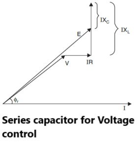
If a static capacitor is connected in series with the line, it reduces the inductive reactance between the load and the supply point and the voltage drop is approximately
IR cos jr + I(XL – Xc) sin jr
It is clear from the vector diagram, that the voltage drop produced by an inductive load can be reduced particularly when the line has a high X/R ratio. In practice Xc may be so chosen that the factor (XL– Xc) sin jr becomes negative and numerically equal to Rcos jr so that the voltage drop becomes zero. The ratio Xc/XL expressed as a percentage is usually referred to as the percentage compensation. If I is the full load current and Xcis the capacitive reactance of the series capacitor then the drop across the capacitor is IXc and the Var rating is I 2Xc. The voltage boost produced by the series capacitor
DV = IXc sin jr
One drawback of series capacitors is the high overvoltage produced across the capacitor terminals under short circuit conditions. The drop across the capacitor is If Xc, where If is the fault current which is of the order of 20 times the full load current under certain circuit condition. A spark gap with a high speed contactor is used to protect the capacitor under these conditions.
Synchronous Capacitors
A great advantage of the synchronous capacitor is its flexibility for use for all load conditions because it supplies vars when over-excited, i.e. during peak load conditions and it consumes vars when under-excited during light load conditions.
There is smooth variation of reactive vars by synchronous capacitors as compared with step by step variation by the static capacitors.
Synchronous machines can be overloaded for short periods whereas static capacitors cannot. For large outputs the synchronous capacitors are much better than the static capacitors from economic viewpoint because otherwise a combination of shunt capacitors and reactors is required which becomes costlier and also the control is not smooth as is achieved with synchronous capacitors.
The main disadvantage of the synchronous capacitor is the possibility of its falling out of step which will thus produce a large sudden change in voltage. Also these machines add to the short circuit capacity of the system during fault condition. A transmission line is said to be a constant voltage or a regulated line if its receiving end voltage is controlled by varying the reactive power at the receiving end when the sending end voltage is kept constant. Other systems where the reactive power available at the receiving end corresponds to the reactive power requirements of the load are termed as unregulated systems.
Tap Changing Transformers
The main job of a transformer is to transform electric energy from one voltage level to another. Almost all power transformers on transmission lines are provided with taps for ratio control i.e., control of secondary voltage. There are two types of tap changing transformers:
(i) Off-load tap changing transformers.
(ii) On-load (under-load) tap changing transformers.
The tap changing transformers do not control the voltage by regulating the flow of reactive vars but by changing the transformation ratio, the voltage in the secondary circuit is varied and voltage control is obtained. This method is the most popular as it can be used for controlling voltages at all levels.
Booster Transformers
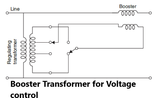
The two-winding load tap changing transformer performs two functions, transforming the voltage and bucking or boosting the voltage whereas the booster transformer performs the latter function only. It can be installed at a sub-station as an additional equipment if voltage regulation is further found to be necessary or it can be installed as a separate piece of equipment at any intermediate point in the line. The latter application maybe desirable on economical or technical grounds to increase the voltage at an intermediate point in a line rather than at the ends as with tap changing transformer.
For small outputs and voltages up to 2000 volts, the simplest booster consists of an autotransformer with necessary tappings, whereas for higher voltages and larger sizes it is necessary to utilize on-load tap changing gear and also to perform the switching in an isolated circuit, the voltage of which is only a fraction of the line voltage. One method is to energize the primaries of the boosting transformers by means of a regulating transformer, the secondary of which is provided with tappings along with tap changing gear as shown in Fig.
The voltage changes are made by means of a motor operated controller and arrangements are made to reverse the connections to the primaries of the regulating transformers so that both buck and boost can be obtained. The sensing device for voltage variation should be sensitive to current rather than voltage as the current varies 100% from no load to full load whereas the voltage varies only by 10% or so.
The following are the advantages of booster transformer:
(i) The transformer can be used at any intermediate point in the system.
(ii) When it is used along with a fixed ratio transformer it can be taken out for inspection or overhaul without affecting much the system.
(iii) The rating of the booster is the product of the current and the injected voltage and is hence only about 10% of that of a main transformer.
The disadvantages of the booster, when it is used in conjunction with the main transformer, are
(i) The two are more expensive than a transformer with on-load tap changing gear.
(ii) They are less efficient due to the losses in the booster.
(iii) They take more floor space.
The booster transformers are normally used in distribution feeders where the cost of tap changing transformer is very high.
I feel this is one of the most important information for me.
And i am glad reading your article. But want to observation on few general things, The web site taste is perfect, the articles
is actually great : D. Excellent activity, cheers http://www.heringstage-wismar.de/2025/03/19/click-to-register-on-22bet-and-create-an-account-just-enter-your-email-and-password-for-all-bonuses-and-mobile-slots-4/
hi,
thanks for appreciation. Now, my focus on spread my website content to more readers.
To boost my moral, Please share my website to your friends and subscribe my Insta/Telegram/Whatsapp group.
Pingback: Operation of high voltage Transmission line
Pingback: Parallel operation of DC link with AC network - Electricalsphere