
Table of Contents
ToggleWhy Neutral Grounding required in Power system?
The neutral grounding is an important aspect of power system design because the performance of the system in terms of the short circuits, stability, protection etc. is greatly affected by the state of the neutral. In most of the modern high voltage systems the neutral of the system is solidly grounded i.e., the neutral is connected directly to the ground without any intentional impedance between the neutral and the ground. Generally the neutral of the generator is connected through resistance to limit the stator short circuit current and also for stability reasons.
Advantages of neutral grounding
(i) Voltages of the phases are limited to phase to ground voltages.
(ii) The high voltages due to arcing grounds or transient line to ground faults are eliminated.
(iii) Sensitive protective relays against line to ground faults can be used.
(iv) The over voltages due to lightning are discharged to ground, otherwise there will be positive reflection at the isolated neutral of the system.
The following are the advantages of operating with isolated neutral:
(i) It is possible to maintain the supply with a fault on one line.
(ii) Interference with communication lines is reduced because of the absence of zero sequence currents
What Is effectively grounded system?
A system or a portion of a system can be said to be effectively grounded when for all points on the system or specified portion thereof the ratio of zero sequence reactance to positive sequence reactance (X0/X1) is not greater than three and the ratio of zero sequence resistance to positive sequence reactance is not greater than one for any condition of operation and for any amount of generator capacity.
The effective grounded systems are less expensive than any other type of grounding for all operating voltages because for such a system the maximum line to ground voltage during a fault does not exceed 80% of the line voltage whereas for all other groundings the voltage of the healthy phases rises to about 100% line-to-line voltage.
Methods of Neutral Grounding
There are various methods of grounding the neutral of the system. They are: (i) Solid grounding;(ii) Resistance grounding; (iii) Reactance grounding; (iv) Voltage transformer grounding; and(v) Zig-zag transformer grounding.
Solid Grounding or Effective Grounding

Consider L-G fault on phase c. The neutral and terminal c are at earth potential. The reversed vector is shown at Vc. The voltage of the healthy phases remains unchanged i.e., phase to ground voltages and the currents areas shown in Fig. The charging current will be fully eliminated.
Since in this system of grounding the voltage of the healthy phases in case of a line to ground fault does not exceed80% of the L-L and is much less as compared to other forms of grounding, the equipments for all voltage classes are less expensive. An 84% lightning arrester instead of 105% can be used.
On system 115 kV and above additional savings are possible because of the transformers with the insulation graded towards the neutral are less costly.
Resistance Grounding

The value of the resistance commonly used is quite high (in order to limit power loss in resistor during L-G fault) as compared with the system reactance. With the increase in operating voltage the value of resistance required for grounding also increases (decreases with capacity) so as to limit (25% of full load current) the short circuit current during line to ground faults. Resistance grounding is normally used where the charging current is small i.e., for low voltage short length overhead lines.
Resistance grounding reduces the arcing ground hazards and it permits ready relaying of ground faults. In certain situations resistance grounding has helped in improving the stability of the system during ground fault by replacing the power dropped, as a result of low voltage, with an approximately equal power loss in the resistor, thus reducing the advance in phase of the generators.
Reactance Grounded System
A reactance grounded system is one in which the neutral is grounded through impedance which is highly reactive. In fact whether a system is solidly grounded or reactance grounded depends upon the ratio of X0/X1.
For reactance grounded systemx0/x1>3
For solid grounded system, x0/x1<3
When a neutral is solidly grounded, but if X0/X1 > 3, the system is presumed to be reactance grounded rather than solidly grounded. Reactance grounding lies between effective grounding and resonant grounding. The value of reactance required is to keep currents within safe limits. This method of grounding may be used for grounding the neutral of synchronous motors and capacitors and also for circuits having large charging currents.
Earthing Transformers
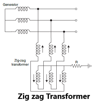
If a neutral point is required which otherwise is not available(e.g., delta connection, bus bar points etc.), a zig-zag transformer is used. These transformers do not have secondary winding (Fig). Each limb of the transformer has two identical windings wound differentially such that under normal conditions that total flux in each limb is negligibly small and, therefore, the transformer draws very little magnetising current.
The grounding transformers are of short time rating usually 10 seconds to 1 minute. Therefore, the sizes of such transformers are small as compared to the power transformers of the same ratings. If a zig-zag transformer is not available, a star delta transformer can be used without loading the delta side.
General Grounding Practice
(i) One grounding is normally provided at each voltage level. Between generation and distribution, there are various voltage levels; it is desirable to have ground available at each voltage level.
(ii) The generators are normally provided with resistance grounding and synchronous motors or synchronous capacitors are provided with reactance grounding.
(iii) Where several generators are connected to a common neutral bus, the bus is connected to ground through a single grounding device. Disconnect switches can be used to ground the desired generators to the neutral bus.
(iv) Where several generators are operating in parallel, only one generator neutral is grounded. This is done to avoid the interference of zero sequence currents. Normally two grounds are available in a station but only one is used at a time. The other is used when the first generator is out of service.
(v) For low voltages up to 600 volts and for high voltages above 33 kV solid grounding is used whereas for medium voltages between 3.3 kV and 33 kV resistance or reactance grounding is used.