
Table of Contents
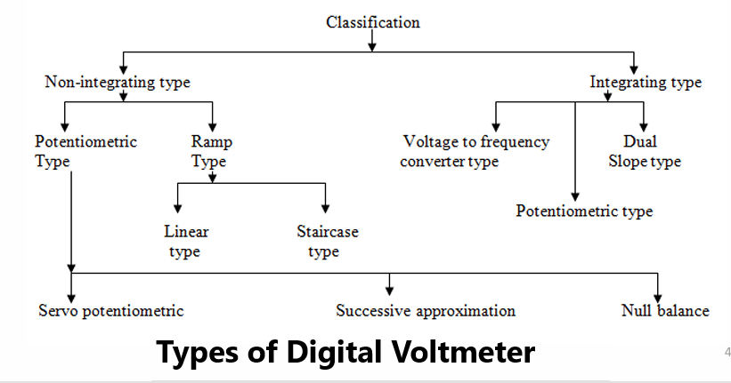
ToggleWhat is Digital Voltmeter?
A digital voltmeter (DVM) displays the value of a.c. or d.c. voltage being measured directly as discrete numerals in the decimal number system. Numerical readout of DVMs is advantageous since it eliminates observational errors committed by operators.
The errors on account of parallax and approximations are entirely eliminated. The use of digital voltmeters increases tile speed with which readings can be taken.
A digital voltmeter is a versatile and accurate voltmeter which has many laboratory applications.
Ramp Type Digital Voltmeter
Its Operating principle is based on the measurement of the time it takes for a linear ramp voltage to rise from 0 V to the level of the input voltage, or to decrease from the level of the input voltage to zero.
This time interval is measured with an electronic time-interval counter, and the count is displayed as a number of digits on electronic indicating tubes.
Block Diagram of Ramp Type Digital Voltmeter
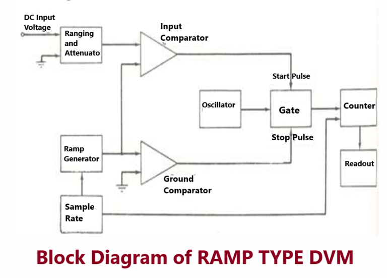
The working principle i.e., the Conversion from a voltage to a time interval is illustrated by the waveform

At the start of the measurement cycle, a ramp voltage is initiated; this voltage can be positive-going or negative-going.
The negative-going ramp, is continuously compared with the unknown input voltage.
At the instant that the ramp voltage equals the unknown voltage, a coincidence circuit, or comparator, generates a pulse which opens a gate.
The ramp voltage continues to decrease with time until it finally reaches 0 V (or ground potential) and a second comparator generates an output pulse which closes the gate.
Potentiometric type DVM
A potentiometric type of DVM employs voltage comparison technique. In this DVM the unknown voltage is compared with reference voltage whose value is fixed by the setting of the calibrated potentiometer.
The potentiometer setting is changed to obtain balance (i.e. null conditions). When null conditions are obtained the value of the unknown voltage, is indicated by the dial setting of the potentiometer. In potentiometric type DVMs, the balance is not obtained manually but is arrived at automatically.
The unknown voltage is filtered and attenuated to suitable level. This input voltage is applied to a comparator (also known as error detector). The reference voltage is obtained from a fixed voltage source. This voltage is applied to a potentiometer.
The value of the feedback voltage depends up the position of the sliding contact. The feedback voltage is also applied to the comparator. The unknown voltage and the feedback voltages are compared in the comparator. The output voltage of the comparator is the difference of the above two voltages.
SUCCESSIVE-APPROXIMATION DVM
The “equal to or greater than” or “less than” decision is made by a comparator. The D/A converter provides the estimate and is compared to the input signal.
A special shift register called a successive-approximation register (SAR) is used to control the D/A converter and consequentially the estimates. At the beginning of the conversion all the outputs from the SAR are at logic zero. If the estimate is greater than the input, the comparator output is high and the first SAR output reverses state and the second output changes to a logic “one.”
If the comparator output is low, indicating that the estimate is lower than the input signal, the first output remains in the logic one state and the second output assumes the logic state one. This continues to all the states until the conversion is complete.
Pingback: Dry type Transformer failure reasons and troubleshooting - Electricalsphere
Pingback: Direct Loading Test on Single Phase Transformer and Three Phase Induction Motor
Pingback: What is Motor Growler test