
Table of Contents
TogglePhase Shifting Transformer (PST)
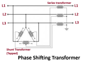
A special kind of transformers like PST or Phase Shifting Transformer is used to control the active power flow on 3-phase transmission networks. This can be done by changing the difference of voltage phase angle among the system nodes. The working principle of a phase-shifting transformer mainly depends on an injection of a phase-shifted voltage source into the line using a series-connected transformer. This can be fed through a shunt transformer.
These two transformer’s configuration mainly induces the phase shift. The construction of a phase-shifting transformer mainly includes two sets of the transformer. The first one is the shunt unit that is connected in parallel through the transmission line whereas the second one is the series unit that is connected within series through the transmission line.
The shunt unit is used to shift the power angle by 90° to apply this power toward the series unit. Lastly, the series unit includes the phase-shifted power toward the transmission line. The modification of phase angle can be done by the blend of connection as well as the position of tap change.
Application of Phase Shifting Transformer
These transformers are used to control the power flow within transmission lines. Other applications are made possible through including series reactive elements targeting at the uprating substation, reserve sharing in the substation, decoupling of the network, control of power flow in line through APSTs (Assisted PSTs) & de-icing of HV transmission lines.
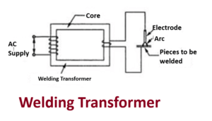
Welding Transformer
- Welding transformer is a step down transformer.
- It has a magnetic core with primary winding which is thin and has large number of turns on one arm.
- A secondary winding with less number of turns and high cross-sectional area on the other arm.
- Due to this type of windings in primary and secondary it behaves as step down transformer.
- So we get less voltage and high current from the secondary winding output. This is the construction of ac welding transformer.
- A dc welding transformer also has same type of winding the only difference is that we connect a rectifier(which converts ac to dc) at the secondary to get dc output.
- We also connect a inductor or filter to smooth the dc current. This will be construction of dc welding transformer. The diagrams are shown below.
Working of welding transformer
- As it is a step down transformer we have less voltage at secondary which is nearly 15 to 45 volts and has high current values which is nearly 200 A to 600 A it can also be higher than this value.
- For adjusting the voltage on secondary side there are tapping’s on secondary winding by this we can get required amount of secondary current for welding.
- These tapping’s are connected to several high current switches.
- Now one end of secondary winding is connected to the welding electrode and the other end is connected to the welding pieces as shown in fig .
- When a high current flows a large amount of I2R heat is produced due to contact resistance between welding pieces and electrode. 6. Because of this high heat the tip of electrode melts and fills the gap between the welding pieces.
Application of welding transformer
Welding Transformers are used in AC machines to change alternating current from the power line into a low-voltage, high amperage current in the secondary winding.
Induction Heating Transformer
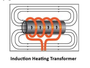
When alternating current flows in a conductor it produces alternating flux. If any other conducting material is placed in this magnetic flux which is alternating, the e.m.f. gets induced in the conducting material. This induced e.m.f. drives eddy currents in that piece. The power loss due to such eddy currents appears as heat. The action of inducing e.m.f. in other material due to alternating flux produced by a current carrying conductor is a transformer action.
Core less type induction heating transformer
It consists of a crucible of cylindrical in shape with refractory lining. Primary winding is wound around a crucible. The molten metal acts as a short circuited secondary. The furnace is generally operated at high frequency. Due to this, skin effect exists which increase effective resistance of primary winding. Due to this there are large copper losses and winding gets heated. So primary winding is made hollow and water is circuited inside for cooling purpose.
Operation of induction heating transformer
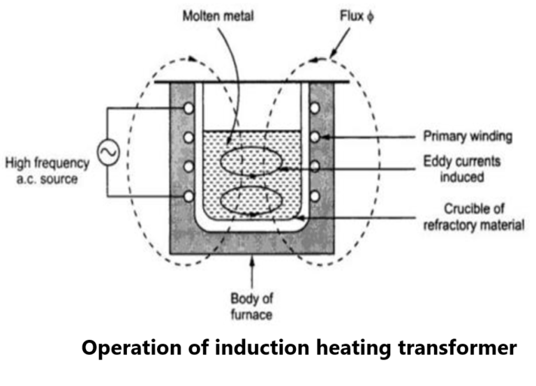
This furnace also operates on the principle of transformer. The primary is connected to an alternating supply of frequency as high as 500 to 600 Hz. The magnetic flux produced by primary sets up eddy current in the molten. This heat is used to melt the molten metal. The l\electromagnetic forces produced does the stirring action.
The operating voltage is about 1000 to 2000 V for larger sizes and up to 10000 V for the smaller sizes. Such induction heating furnaces have ratings varying from 15 KVA to 40000 KVA. As power rating increases, the operating frequency decreases. The power factor of such furnaces is very low (about 0.2) as magnetising current required is large to drive the flux through molten metal and air. To improve the power factor capacitor bank is required.
Applications of induction heating transformer
- induction heating furnaces are often used to manufacturer high grade steel.
- To melt the various alloys.
- To melt the metals like aluminium, copper and iron
Furnace Transformer
A furnace is a device which is used for heating, and the industrial furnace is used for many purposes, such as the extraction of metal from ore, or in oil refineries and other chemical plants. There is much qualitative range of furnace transformer that is manufactured and designed using cutting edge technology. Mostly furnace transformers are used in steel plants and aluminum industries.
These come with various distinguishing factors that provide them superior functioning rates and durability. These transformers are available with automatic on and off cooling facilities in various sizes with on-load tap changers.
Furnace transformers are used to convert mains voltage to power electronics in the electrical appliances. These transformers are widely available in different power ratings. Furnace transformer will adapt electrical energy to the requirements of the electrical furnaces.
Difference between electric arc furnace and induction furnace
Induction furnace is used for both ferrous and non-ferrous melting applications, induction furnace exhibits good melt agitation, relatively easy fume control and rapid heat-up. It is not as dusty as electric arc melting, it only produces 20 percent as much effluent dust. In general induction furnace will create less pollution when compared to the electric arc furnace.
Types of furnace transformer
Arc furnace transformer
In many industrial applications arc furnace is used for example in the steel industry they are used to smelting scrap iron and for refining steel. They are also used for other applications such as smelting glass and ceramics, manufacturing and refining of many materials. Electric arc furnace can be either AC or DC and the power ratings of these transformers are 20 – 200MVA. Reactors are used to smoothen the fluctuations, either in the same tank or in a separate unit.
AC arc Furnace transformer
Ac arc furnace transformer can be used for long arc and short arc operations. These types of electric arc furnace transformers are used for many different furnace processes and applications. These types of transformers are used for steel furnaces, ladle furnaces and smelting of other materials steel arc furnace does its operation under severe conditions. With regard to frequent over-voltages and over-currents generated by the short circuits in the furnace and the operation of the HV circuit breaker. They have cyclic loading but in case of other applications loading is continuous at high utilization.
DC arc furnace
DC furnace transformer needs to withstand the stresses of furnace operation and it also needs to withstand other stresses which are related to the rectifier operation. This transformer behaves as a rectifier transformer for furnace operation. The HV side needs to be protected from frequent switching over-voltages. Most large DC furnaces are made for steel production. The use of the thyristor rectifier for the conversion to DC normally reduces the requirement for on-load voltage regulation of the furnace transformer. The step voltage is larger than the AC voltage, and a no-load tap changer is adequate in many applications.
Pingback: Dry type Transformer failure reasons and troubleshooting
Pingback: Auto Transformer: Working Principle, Advantage, Application
Pingback: What Is Earthing Transformer and their connection diagram
I do agree with all of the ideas you have presented in your post. They are very convincing and will definitely work. Still, the posts are very short for starters. Could you please extend them a little from next time? Thanks for the post.
I don’t think the title of your article matches the content lol. Just kidding, mainly because I had some doubts after reading the article. https://accounts.binance.com/pt-BR/register-person?ref=GJY4VW8W
Your point of view caught my eye and was very interesting. Thanks. I have a question for you. https://www.binance.com/register?ref=QCGZMHR6