Table of Contents
Toggle11kV Vacuum Circuit Breaker (VCB) Panel Design
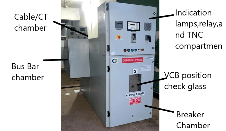
It’s metal parts divided into below comparnmet:
Circuit breaker compartment.
Busbar compartment.
Cable/C.T. compartment
Instrument compartment
Circuit breaker compartmet
The circuit breaker compartment contains a draw out / withdraws able truck with vacuum circuit breaker.
The withdrawable truck moves on two in-built foldable ramps. It can be transferred between the connected and test positions behind close door of circuit breaker chamber using a hand crank.
In the connected (Service) position, the upper contact feeder arms of the with drawable truck engage with mating contacts connected to the outgoing circuit.
In the test & service positions, the contact arms and their mating contacts are separated by independently operated metallic shutters operated by the truck movement. In the disconnected (isolated) position, LV plug is removed.
Drive mechanism of the truck is connected to the cubical frame using bolt arrangement, to remove the withdrwable truck from the cubicle; the bolting of drive mechanism of truck should be removed.
Busbar compartment
The busbar compartment contains:
The busbar, bushing with encapsulated feeder connections.The busbar are extending from one switchgear cubicle to the next. The ends of this sections are bolted to terminal pad of encapsulated feeder connections.
Cable & C.T. compartment
The cable compartment contains:
Insulating bushing with mating contacts for the lower contacts arms of the withdrawable part, Cable connecting terminals, section of the main earth busbar and Current transformers. The terminals are accessible from the rear.
Instrument Compartment
This compartment houses all the law voltage devices ( protective relays, MCBs, Control terminal, etc) Indicating lamps, meters, push buttons, relays and control switches are mounted flush with instrument chamber door.
11kV VCB panel Interlock
The circuit breaker cannot be inserted in to ‘SERVICES’ position when it is in ‘CLOSED’ position
The circuit breaker can not be withdrawal from the ‘SERVICE’ position, unless it is in ‘OPEN’ position.
The circuit breaker can be closed only in ‘TEST’ and in ‘SERVICE’ position.
VCB of lower rating cannot be inserted in to the panel of VCB of higher rating.
VCB cannot be put in to service unless the multiple plug is in position.
The door can only be opened when breaker is in ‘OFF’ position or vice a versa.
The operation shall be possible only with closed door condition.Racking in/out operation should be possible only when front panel door is closed.
Vacuum Circuit Breaker(VCB)
Vacuum circuit breaker incorporates a specially designed and completely sealed vacuum interrupter to perform its basic function of opening as well as closing when called to upon to do so. Closing and opening operation perform in both under normal operating conditions and under fault condition such short circuit.
The vacuum circuit-breaker consists of the mechanism housing, the 3-pole assemblies with vacuum interrupters, U-shaped barrier (Encapsulated housing). Which ensure stable mounting of the vacuum interrupters and also provides adequate inter-phase and phase to earth segregation.
The barrier is mounted on the rear side of the VCB mechanism cabinet. The mechanism housing accommodates all electrical & mechanical element required for opening and closing the vacuum circuit breaker. The mechanism housing has a detachable cover which has cut-outs for the equipment level of the circuit breaker.
Vacuum Interrupter (VI bottle)

The fixed contact piece is connected directly to the housing. The moving contact piece is fixed connect to the terminal bolt and is located centrally in the guide. The metal bellows together with insulators made of high alumina ceramics and the end flanges form the vacuum-proof interrupter housing.
A spring operating mechanism mounted inside a sheet steel cabinet is used to provide energy required for breaker operation. The closing spring, which are charged manually or through a motor, provide the energy for closing the vcb and for applying sufficient contact pressure on the moving contacts of vacuum interrupters through the wipe springs, which get charged on closing the VCB, provide energy for opening the VCB.
The mechanism energy is transmitted to the vacuum interrupters via insulating links during closing well as opening. There is a dash pot in the mechanism which provides sufficient damping during the opening operation of the VCB.
The VCB is provided with open /closed and charged/discharged indicators on its front side. A green color push button is provided for manually closing and red color push button is provided for manually opening of VCB. When VCB is received at site it is in open condition and the spring is discharged.
A charging handle is provided in the front for manual spring charging. Two handle provided on the sides for moving the VCB. At the upper center of the VCB cabinet front cover, an opening is provided for inserting the driving handle to rack in/out the VCB. On the bottom left hand corner, a provision has been made for inserting the multi-pin plug socket.
The closing coil, tripping coil and breaker operated auxiliary switch is provided in mechanism cabinet.The moving contacts of the vacuum interrupter is connected to the bottom disconnecting arm through flexible jumpers, the fixed contact of the vacuum interrupter is assembled with the top disconnecting arm.
The jaw contacts, fixed at the end of the disconnecting arms, are made of specially designed copper strip which are assembled together and are spring loaded. This ensures sufficient contact pressure when the jaw contacts get engaged with the contacts blades on the panel while the VCB is in SERVICE.
VCB Spring Charge Operation
Initially when the VCB received at site is OPEN and closing springs are DISCHARGED. Charging of closing springs is done either manually or electrically through a motor. The CHARGED / DISCHARGED indicator shows the status of the closing springs.
Manual charging
Hold the charging handle and move it by approximately 30 degrees till it steps. This will rotate gear which in turn will rotate gear cum shaft. The closing springs. Which are hinged at one end. Will get start getting charged due to crank fitted on the cam shaft.
Now return the charging handle back to its original position and move it up again. Repeat this till the spring is fully charged. A distinct clicking sound will heard as soon as springs are fully charged and the CHARGED / DISCHARGED indicator changes over CHARGED position. The VCB is now ready for closing.
In order to prevent overcharging “stop” the handle movement as soon as a distinct ‘click’ sound is heard and indicator changes over the CHARGED position. Over charging can damage the mechanism.
The number of time the charging handle is to be moved up and down for full charging of closing springs depends of the angle of the handle movement. If the movement of manual spring charging handle in kept to about 30 degree every time, approximately 14 strokes will be required for full charging.
Electrical Motor charging operation
As soon as electrical supply is given to the charging motor, it will rotate the shaft which is turn will rotate the gear. The remaining charging operation is similar to manual charging.
When the springs are about to get charged fully, the cam mounted on the cam shaft will operate the micro switch through lever. And supply to the motor will be not cut off. The motor takes about 6 to 8 seconds to charge the spring.
The closing springs will get automatically recharged through the spring charging motor as soon as they get discharged on closing of the breaker.
VCB Closing operation
When the springs are fully charged, the linkages attain position. now the VCB is ready for closing operation.
Manual closing
Push the closing push button. The closing shaft will turn about its axis, thus releasing the closing catch. Now, energy of the closing spring will cause the cam to rotate at fast speed and bring linkages to position.
The rotation of cam will turn the main shaft and the breaker will get charged during closing operation. The breaker position indicator changes over to DISCHARGED.It is possible to re-change the spring in the position.
Electrical closing
When supply is given to closing coil the plunger of closing coil will push the closing paddle. This will cause the closing shaft to turn.
The remaining closing is similar to manual closing operation. The supply to motor is re-connected immediately on closing of the breaker due to rotation of cam, lever & micro switch and the closing spring get recharged and linkages attain the position.
The breaker position indicator changes over to CLOSED, and after immediate re-charging, the charging will show CHARGED.
VCB Opening operation
When the VCB is CLOSED, the linkages attain the position, and the breaker is ready for opening.
Manual opening
Push the trip push button. This will turn the trip shaft through tripping paddle, which in turn will release the tripping catch. The energy of opening spring and wipe spring will cause the linkages to attain the position.
This movement of linkages will turn the main shaft and the circuit breaker will OPEN. During opening operation, initially, energy of wipe springs will be release to attain the required initial speed. The same will be further maintained by the release of opening spring energy.
Electrical opening
Shunt trip:When supply is given to tripping coil, the plunger of tripping coil will push the tripping shaft, causing it to turn. The remaining operation is similar to manual opening operation.
Auto re-closing feature: The Vacuum circuit breaker is provided with a facility for auto-re-closing. This feature is achieved since it is possible to charge the closing springs as soon as they get discharged during closing operation. The mechanism is thus kept ready to re-close the VCB as soon as it is opened.


Pingback: Interview and short exam Question for Electrical engineer-PART-1
Pingback: HVDC Circuit breaker: Working, Types and Application
Pingback: Types of Circuit Breaker and their working principle