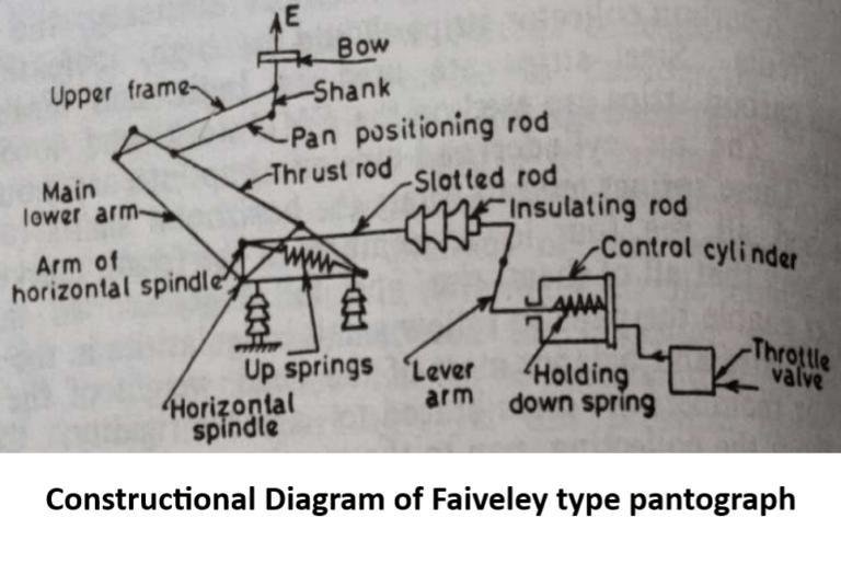
Constructional Diagram of Faiveley type pantograph

In the case of 25 kV a.c traction system the contact wire of OHE is of light section. This would mean low contact pressure of 6.5 to 9 kg. Pantographs for a.c traction system are, therefore, light weight single aided Faiveley pattern shown in Fig. It consists of a
sub frame or base,
articulated system,
pneumatic control system including throttle valve,
two raising springs and
four insulators.
The base is made up of welded sections and houses two ball bearings on which carried the articulated system. Rubber stops are provided to limit the folding of the articulated system at the lower part.
Articulated system consists of:
(a) horizontal spindle turning into two ball bearings which are the part of the base.
(b) lower arm integral with horizontal spindle and supporting at the upper end bearingon which are fitted two tubes of the upper frame.
(c) thrust rod articulated at lower end on fixed point of the base frame and on upper end on bearing housed in the ‘yoke’ casting at the upper end of lower arm. Thrust rod ensures the positioning of the upper frame as lower arm rotates.
(d) transversal tube rotating in the sleeves fitted on the tube ends of upper frame. Pan positioning rod is connected to the transversal tube through shank which is welded to it. At the end of transversal tubes are fitted spring boxes which form resilient support to the bow.
(e) Positioning rod, articulated on a pin fitted on the thrust rod end on one side and on the crank pin fitted to the shank as shown in Fig. on the other side, keeps the contact plane horizontal during vertical movements of the bow.
Two up springs are hooked on one side to balancing member attached to the base and on the other side to the arm of horizontal spindle.
Tension in these springs balances the mass of articulated system and also ensures pantograph raising and producing con tact force. Piston in the control cylinder is held back by the holding down springs.
Admission of air under pressure to the cylinder operates the piston rod which in turn operates the lever arm. This produces translator motion of the insulating rod and slotted rod. Control cylinder is earthed and fitted separately from the base on the vehicle roof. Compressed air enters the control. Cylinder through throttle valve.
The admission and escape of air are adjusted so that raising and lowering can be done without shock either on the contact wire Bow as shown in Fig. 6.5(b) and (c) consists of frame on which are bolted two collecting strips. Intermediate parts or on the base.
Join the frame with the horns. The bow is fitted on resilient spring box through rods with fork. Whole of the pantograph is fitted on the roof of the vehicle by means of four insulators.
Working of Faiveley type pantograph
When compressed air is admitted in the control cylinder, piston compresses the holding down springs and slotted rod gets translatory motion which permits horizontal spindle to rotate under the action of upsprings.
The pantograph then rises until collector touches the OHE. The articulated system then stops and piston complete its stroke. From this point onward the air motor plays no further part and piston remains stationary during normal operation.
The pin of the horizontal spindle is permitted to move freely in the slot of slotted rod and pantograph is operated purely by up springs. This design permits free movement of articulated system throughout the full distance of its rise and fall.
Opening of the control cylinder to atmosphere causes piston to return under the force of holding down springs.Slotted rod presses on the pin of the horizontal spindle thereby lowering the articulated system

You made a number of good points there. I did a search on the subject and found mainly folks will agree with your blog.
Magnificent web site. Lots of useful info here. I’m sending it to several friends ans additionally sharing in delicious. And of course, thank you on your sweat!
Very well explained