

Table of Contents
ToggleFullname of HVDC CB
High Voltage Direct Current Circuit Breaker (HVDC CB)
Definition of HVDC Circuit breaker
Circuit breakers will be positioned on DC grids and act when a fault occurs. Breakers would have to fulfill some basic requirements. Current zero crossing should be created to interrupt the current once a fault occurs. At the same time the energy that is stored in the system’s inductance should be dissipated and the breaker should withstand the voltage response of the network.
In A. C. circuit breakers, arc extinction is achieved at the natural current zero of the a.c. waveform used. But in D. C. circuit breakers, natural zero of voltage and current is not available as both are continuously available. Thus for extinction of an arc, artificial current zero is required to be introduced.
Introduction
HVDC transmission and how this technology is used to create multi-terminal networks that can be used to connect different power stations in a more efficient way than AC transmission.
HVDC circuit breakers are fundamental to the operation of such networks, due to their ability to prevent faulty situations. Research will be done on the operation of breakers, their limitations and how these can be used in DC grids.
High Voltage Direct Current has been used for decades for transmission of power over long distances. The fact that capacitance in cables doesn’t cause losses means that it makes up for drawbacks in the conversion process from AC.
HVDC conversion stations are more expensive than the AC ones. On the other hand, long distance HVDC lines cost in general less than the respective AC lines.
DC breakers or Metallic Return Transfer Breakers (MRTB) are used, if required for interruption of rated load currents. In addition to the DC switchgear, AC switchgear and associated equipment for protection and measurement are also part of the converter station.
Requirement for HVDC Circuit Breaker
The HVDC circuit breaker operation & design is complex as compared to AC circuit breaker due to the absence of natural zero crossing. The arc generated in HVDC will never extinguish & it will heat up the contacts of the breaker & eventually destroy the contacts rendering the whole CB useless.
The circuit will still be complete & the equipment connected will get damaged due to the fault current. Therefore, the following requirement must be completed to ensure safe circuit breaking in HVDC circuit breaker,
Creation of artificial zero crossing
Dissipation of the stored energy inside the LC circuit
Withstanding the voltage between its contact
Prevention of arc restriking
In order to fulfill the above requirements, an LC circuit is introduced with the circuit breaker in parallel which will generate artificial zero current across the line to safely break open the circuit.
The strength of the arc is directly proportional to the voltage level & the current. Therefore the fault current must be brought down to zero using an external circuit before breaking it.
Comparison of AC Circuit Breaker & DC Circuit Breaker
The AC current fluctuate along zero line offering many natural zero crossing almost 100 times in a second at the 50 Hz. Therefore, the AC circuit breaker utilizes this feature of AC to extinguish the arc when the current is at zero point.
The alternating current changes its direction continuously which offers to allow multiple chances to extinguish the arc. On the other hand, the DC current stays in steady state & there is no chance of natural zero current. The arc generated in DC circuit breaking does not extinguish since the current never reached zero point.
Therefore, the DC circuit breaker utilizes extra circuitry to introduce artificial zero currents in the line to extinguish the arc. This is why DC circuit breaker are complex in design as compared to AC circuit breaker.
AC/DC conversion technologies have improved greatly recently, in order to operate a practical HVDC grid, circuit breaker technology still doesn’t exist to satisfactorily isolate a single branch line of the grid, meaning that the whole grid would have to be shut down in the event of a malfunction.
This means that development of a successful HVDC circuit breaker would be a significant breakthrough for the future of power transmission.
HVDC circuit breaker Working Principle
An artificial current zero is possible by connecting LC circuit in parallel with the circuit breaker. The LC circuit is responsible to produce oscillatory arc currents having many artificial current zeros. At one of the artificial current zero arc gets extinguished.

As shown Fig-A, pre-charged capacitor C is connected having reversed polarities as shown in the figure. An inductor L & a switch S is connected in series with the capacitor C. this extra circuit is connected in parallel with the main breaker M.

As shown in Fig-B, Under normal conditions, the switch S is open & the main breaker M is closed & the current flow through it. During current interruption or fault current conditions, the switch S is closed which completes the LC circuit & the main breaker M is opened.
During this time, the capacitor C start discharging & it pushes the current in reverse direction through the breaker M, forcing the arcing current to oscillate (reaching to zero point) which results in artificial commutation or zero crossing. This artificial zero commutation generated by the LC circuit allows the arc to extinguish at zero current point. The extra energy is dissipated with in the LC circuit.
This type of DC circuit breaker can work on a single power line & does not require the second opposite polarity line.
Method-2
Another method of arc quenching in HVDC circuit breaker is explained using the following design that uses both lines of a DC transmission.
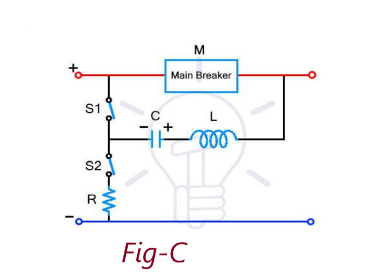
As shown in Fig-C, the Main breaker M is connected on the live or hot line. An LC circuit is connected in parallel with the main breaker M using two switches S1 & S2 . The S2 switch connects the LC circuit to the ground through a high resistance R.

As shown on Fig-D,Under normal condition, the main breaker M & the switch S2 is closed, while the S1 is open. The current flows through the main breaker M to the load & also through the switch S2 to charge the capacitor. The capacitor is charged through the high resistance.
During current interruption or fault current, the switch S2 is opened & the S1 is closed. The charged capacitor starts discharging the current in reverse direction through the main breaker M. The LC circuit starts resonating & creates oscillating current that forces the current through the main breaker M to cross zero.
The main breaker M contacts separate at this zero current, resulting in the extinction of the arc. As soon as the M contacts open, the switch S2 is closed & S1 is opened. The S2 allows the extra energy to dissipate in the heavy resistance R. This prevents the arc from re-striking.
Types of HVDC Circuit-Breakers
There are two types of HVDC circuit breakers: electromechanical and solid-state.
Electromechanical HVDC Circuit breaker
Electromechanical can be grouped into three categories: (1) inverse voltage generating method, (2) divergent current oscillating method, and (3) inverse current injecting method.
Only the inverse current injecting method can be used in high voltage and current ratings. In this type of breaker, current zero can be created by superimposing an inverse current (of high frequency) on the input current by dis-charging a capacitor (that was precharged) through an inductor.The cost of components required for an electromechanical DC circuit breaker would not be significantly higher than that of an AC circuit breaker.
Electromechanical HVDC circuit breakers are available up to 500 kV, 5 kA and have a fault-clearing time of the order of 100 ms.
Solid state HVDC Circuit breaker
These breakers can interrupt current much faster (which is required in some cases) than electromechanical circuit breakers, having an interruption time of a few milliseconds.
They are based on Integrated Gate Commutated Thyristors (IGCT), which compared to IGBT (bipolar thyristors) have lower on-state losses. Current flows through the IGCT and in order to interrupt, the IGCT is turned off. Once that happens, voltage quickly increases until a varistor (that is in parallel to the thyristor) starts to conduct.
The varistor is designed to block voltages above the voltage level of the system. The main disadvantages of these types of circuit breakers are the high on-state losses and the capital costs.
Typical ratings of solid-state circuit breakers in operation are 4 kV, 2 kA, although in ratings of up to 150 kV, 2 kA were considered.
Application of DC circuit breaker over AC circuit breaker
Bulk power transmission over long distances is an application ideally suited for DC transmission and is more economical than ac transmission. So DC Circuit breaker used at station.
Conclusion
HVDC is a technology with continuous advancements and it is going to be dominant in the next few years. The potential change from CSC to VSC is going to make HVDC much more efficient, since VSC can offer higher efficiency, faster switching and by using less components make systems smaller and cheaper.
VSC can make the change in power flow much easier, it will allow the creation of HVDC grids, multi-terminal networks that are much more efficient than point to point HVDC transmission and AC grids.
The creation of such grids depends on the development of HVDC circuit breakers that can efficiently handle fault situations in such high voltage ratings and currents. Electromechanical breakers can work up to a few hundreds of kilo-volts, but changes are required so that they can cost less and interrupt faster than they do at the moment.
Pingback: Advantages of D.C Transmission - Electricalsphere
I think other website owners should take this web site as an model, very clean and excellent user pleasant style and design.