
Table of Contents
ToggleIntroduction
Electric power transmission was originally developed with direct current. The availability of transformers and the development and improvement of induction motors at the beginning of the 20th century, led to the use of AC transmission.
DC Transmission now became practical when long distances were to be covered or where cables were required. With the fast development of converters (rectifiers and inverters) at higher voltages and larger currents, DC transmission has become a major factor in the planning of the power transmission.
In the beginning all HVDC schemes used mercury arc valves. About 1960 control electrodes were added to silicon diodes, giving silicon controlled- rectifiers (SCRs or Thyristors). Today, the highest functional DC voltage for DC transmission is +/- 600kV. D.C transmission is now an integral part of the delivery of electricity in many countries throughout the world.
Comparison of AC and DC Transmission
In DC transmission, inductance and capacitance of the line has no effect on the power transfer capability of the line and the line drop. Also, there is no leakage or charging current of the line under steady conditions.
A DC line requires only 2 conductors whereas AC line requires 3 conductors in 3-phase AC systems. The cost of the terminal equipment is more in DC lines than in AC line. Break-even distance is one at which the cost of the two systems is the same. It is understood from the below figure that a DC line is economical for long distances which are greater than the break-even distance.
A DC link allows power transmission between AC networks with different frequencies or networks, which cannot be synchronized, for other reasons.
Inductive and capacitive parameters do not limit the transmission capacity or the maximum length of a DC overhead line or cable. The conductor cross section is fully utilized because there is no skin effect.
The power transfer in an AC line is dependent on the angle difference between the voltage phasors at the two line ends. For a given power transfer level, this angle increases with distance. The maximum power transfer is limited by the considerations of steady state and transient stability.
The power carrying capability of an AC line is inversely proportional to transmission distance whereas the power carrying ability of DC lines is unaffected by the distance of transmission.
Types of HVDC link
For connecting two networks or system, various types of HVDC links are used. HVDC links are classified into three types. These links are explained below:
Bipolar link
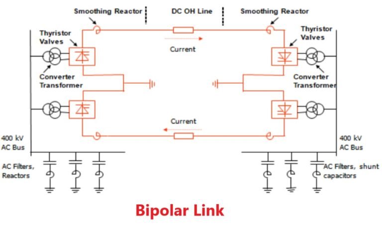
The Bipolar link has two conductors one is positive, and the other one is negative to the earth. The link has converter station at each end. The midpoints of the converter stations are earthed through electrodes. The voltage of the earthed electrodes is just half the voltage of the conductor used for transmission the HVDC.
Monopolar link
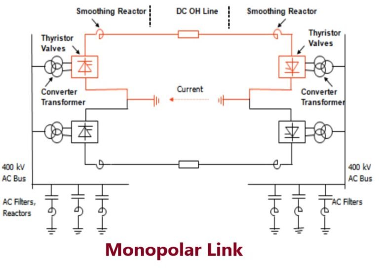
It has a single conductor of negative polarity and uses earth or sea for the return path of current. Sometimes the metallic return is also used. In the Monopolar link, two converters are placed at the end of each pole.
Earthling of poles is done by earth electrodes placed about 15 to 55 km away from the respective terminal stations. But this link has several disadvantages because it uses earth as a return path. The monopolar link is not much in use nowadays.
Homopolar link
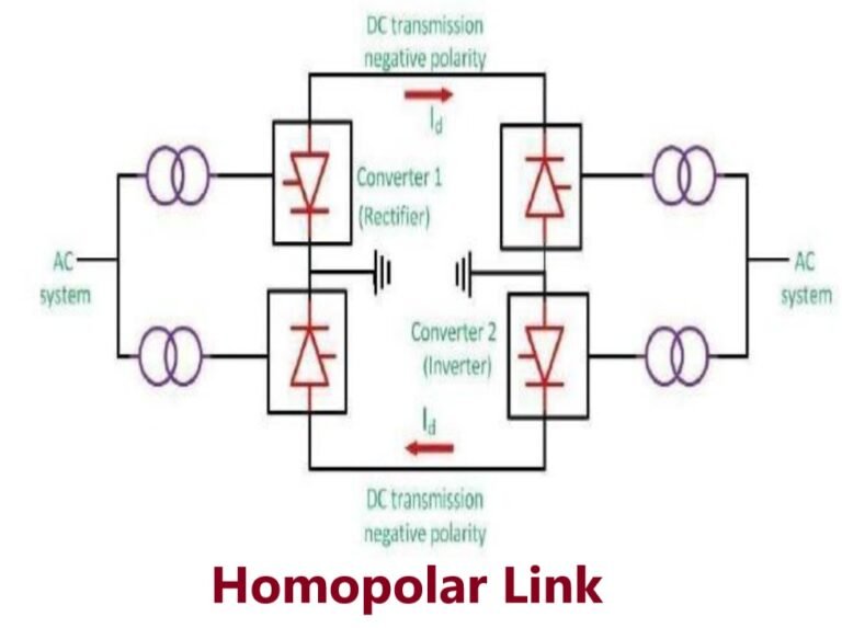
It has two conductors of the same polarity usually negative polarity and always operates with earth or metallic return. In the homopolar link, poles are operated in parallel, which reduces the insulation cost. The homopolar system is not used presently.
Components of HVDC
Converter Station
- Converter Unit
- Converter Valves
Converter Transformers
Filters
- AC filter
- DC filter
- High-frequency filter
Smoothing Reactor
HVDC System Pole
Earth electrodes
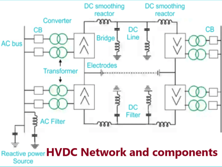
Converter Station
The terminal substations which convert an AC to DC are called rectifier terminal while the terminal substations which convert DC to AC are called inverter terminal. Every terminal is designed to work in both the rectifier and inverter mode.
Therefore, each terminal is called converter terminal, or rectifier terminal. A two-terminal HVDC system has only two terminals and one HVDC line.
Converter unit
The conversion from AC to DC and vice versa is done in HVDC converter stations by using three-phase bridge converters. HVDC transmission a 12-pulse bridge converter is used. The converter obtains by connecting two or 6-pulse bridge in series.
Converter Valves
The modern HVDC converters use 12-pulse converter units. The total number of a valve in each unit is 12. The valve is made up of series connected thyristor modules. The number of thyristor valve depends on the required voltage across the valve. The valves are installed in valve halls, and they are cooled by air, oil, water or Freon.
Converter transformer
The converter transformers transform the voltage of the AC bus bar to the required entry voltage of the converter.
The 12-pulse converter requires two 3-phase systems which are spaced apart from each other by 30 or 150 electrical degrees. This is achieved by installing a transformer on each network side in the vector groups star – star and star-delta.
The transformer is an interface between AC side and DC side. The converter transformers are equipped with on-load tap-changers in order to reduce the stressed, by both the AC voltage and the direct voltage potential between valve-side winding and ground provide therefore the correct valve voltage is obtained. Generally a bridge converter is of 6-Pulse in nature so the transformer can be 3Ф or three 1Ф transformers.
But for HVDC a 12 pulse converter is needed so two 6 pulse are connected in series
- Six 1Ф 2 winding Transformer
- Three 1Ф 3 winding Transformer
- Two 3Ф Transformer
It is not possible to use the winding close to the yoke as the potential of winding connection is determined by conducting Valve. When some valves are operating they produce harmonics. So these harmonics pass through the transformer so the winding have to be insulated properly.
When the valves are in non conduction states they experience PIV and this voltage replicated at the converter transformer so to protect the transformer from this higher voltagesthey should be properly insulated.
As the DC currents flow in the windings of the transformer there is problem of saturation. As the leakage fluxes of a converter transformer contain high harmonics it produces eddy currents, hysteresis loss and hot spots in the transformer tanks.
Since under fault the fault current flows through the transformer impedance , so to limit this high current the impedance of the transformer should be high. Transformer is of the OLTC ( On Load Tap Change)
Smoothing reactor
Smoothing reactor is an oil filled oil cooled reactor having a large inductance. It is connected in series with the converter before the DC filter. It can be located either on the line side or on the neutral side. Smoothing reactors serve the following purposes.
- They smooth the ripples in the direct current.
- They decrease the harmonic voltage and current in the DC lines.
- They limit the fault current in the DC line.
- Consequent commutation failures in inverters are prevented by smoothing reactors by reducing the rate of rising of the DC line in the bridge when the direct voltage of another series connected voltage collapses.
- Smoothing reactors reduce the steepness of voltage and current surges from the DC line. Thus, the stresses on the converter valves and valve surge diverters are reduced.
Filters
There are three types of filters used which are
AC Filters: These are passive circuits used to provide low impedance, shunt paths for AC harmonic currents. Both tuned and damped filter arrangements are used. The AC harmonic filter also provided a reactive power required for satisfactory operation of converters.
DC Filters: These are similar to AC filters and are used for the filtering of DC harmonics.
High Frequency (RF/PLC) Filters: These are connected between the converter transformer and the station AC bus to suppress any high frequency currents. Sometimes such filters are provided on high-voltage DC bus connected between the DC filter and DC line and also on the neutral side.
Reactive power source
Under Emergency condition ground Return Path is used.
Earth Resistivity is generally high in the order of 4000 Ω-m.
Earth electrode cannot be kept directly on the earth surface.
Electrodes are to be buried deep in the ground where the resistivity is (3-10Ω-m) to reduce transient over voltages during line faults and also gives low DC electric potential and potential gradient at the surface of the earth.
HVDC System Pole
The HVDC system pole is the part of an HVDC system consisting of all the equipment in the HVDC substation. It also interconnects the transmission lines which during normal operating condition exhibit a common direct polarity with respect to earth.
Advantages of DC transmission
During bad weather conditions, the corona loss and radio interference are lower for a HVDC line compared to that in an AC line of same voltage and same conductor size.
Due to the absence of inductance in DC, an HVDC line offers better voltage regulation. Also, HVDC offers greater controllability compared to HVAC.
AC power grids are standardized for 50 Hz in some countries and 60 Hz in other.
It is impossible to interconnect two power grids working at different frequencies with the help of an AC interconnection. An HVDC link makes this possible.
Interference with nearby communication lines is lesser in the case of HVDC overhead line than that for an HVAC line.
Power flow control is easy in HVDC link.
DC transmission have High reliability.
Disadvantages of DC transmission
High cost of conversion equipment.
Inability to use transformers to alter voltage levels.
Generation of harmonics.
Requirement of reactive power
Complexity of controls.
Frequently Asked Question (FAQ)
What is HVDC transmission?
HVDC (High Voltage Direct Current) transmission is a method of transmitting electrical power over long distances using direct current (DC) rather than alternating current (AC). It is employed for efficient and reliable power transmission over large distances, underwater cables, and interconnecting asynchronous AC systems.
How does HVDC transmission work?
HVDC transmission involves converting AC power from a power station into DC power using rectifiers, transmitting the DC power over long distances with minimal losses, and then converting it back to AC using inverters at the receiving end. This process allows for the efficient transmission of electricity over long distances and interconnection of different AC grids.
What are the components of an HVDC link?
An HVDC link typically includes converter stations (with rectifiers and inverters), transmission lines, and AC and harmonic filters.
What are the advantages of HVDC transmission?
Advantages include lower transmission losses, interconnection of asynchronous AC systems, enhanced control over power flow, reduced environmental impact, and efficient integration of renewable energy sources.
Where is HVDC transmission commonly used?
It’s commonly used for long-distance transmission, underwater and underground transmission, integrating renewable energy sources, and interconnecting different AC grids.
What are the challenges of HVDC transmission?
Challenges include high initial costs, complexity of control systems, limited transmission routes, potential for electromagnetic interference, and technical challenges in voltage and current control.
Where is HVDC transmission commonly used?
HVDC transmission is commonly used in various applications, including:
- Long-distance transmission of electricity, such as connecting remote power generation sites to urban centers.
- Underwater and underground transmission, such as submarine cables and interconnections between islands or across continents.
- Integration of renewable energy sources, such as offshore wind farms and remote hydroelectric plants.
- Interconnection of different AC grids, especially in regions with asynchronous power systems.
Pingback: Advantages of D.C Transmission - Electricalsphere
Pingback: How to control Frequency in DC Transmission
Pingback: Interview Question on Transmission and Distribution