Table of Contents
ToggleCircuit Breaker Insulation Resistance Test

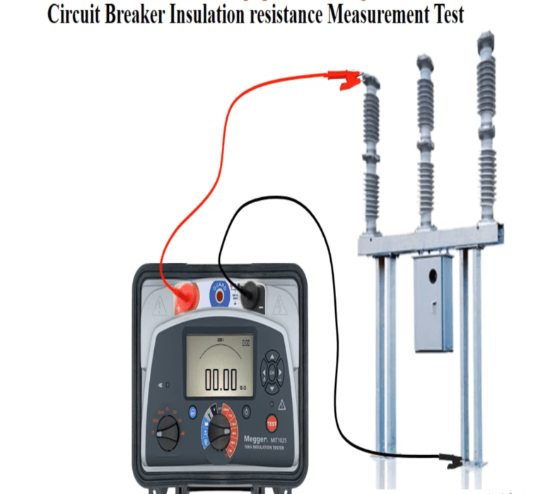
Use Megger to measure insulation resistance.
Insulation Resistance Tests to be done:
Pole – Pole ( CB in open position )
Phase-Earth (CB in Closed Condition)
Phase to Phase(CB in closed condition)
The IR value should be > 500 MΩ
Circuit Breaker Timing Test

Closing time: The time interval between energizing the coils of the breaker (when CB contacts are in open position) and the instant when the contacts touch each other.
Opening time: It is opposite to that of closing time. It is the time interval between energizing the trip coil (CB contacts are in open position) and the instant when contacts separate from each other.
Procedure
De- energize, discharge the equipment which is to be tested as a safety precaution.
Check whether Timer leads and associated clips that are to be connected to the breaker poles are good & tight.
Make the test connections on the lines of circuit diagram
Switch on the power supply to the timer and issue Close command from the timer. Note down the close timing displayed on the timer
After recommended time interval (3 seconds), issue Open command from the timer. Note down the open timing displayed on the timer.
Now issue Close-Open (CO) command from the timer. Note down the CO timing displayed on the timer.
Circuit Breaker contact resistance test

Due to the making and breaking of contacts at high speed and pressure, the contacts can be damaged.
Due operation of breaker, sparking occurs which can depreciate the contacts.
Sparking results in carbon formation which accumulates on the surface of contact and can increase in its resistance.
Due to increase in resistance of contacts, the I2R losses increase. Rise in contact resistance illustrates some abnormality in contacts of breaker therefore contact resistance test is performed.
Operating principle of this test depends upon balancing bridge (like Wheatstone bridge) and Ohms law. High current is injected and small voltage is applied to measure contact resistance.
Testing procedure
De-energize and discharge equipment which is to be tested as a safety precaution.
In case of the breaker make sure that Breaker/ isolated is isolated and kept in closed condition.
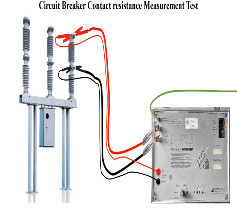
Make all the contact clean & connect current / voltage lead as shown below
Check the Firmness of the connections as loose connections may give erroneous results.
Switch on the power supply to the CRM and wait for the displayed values to become steady.
Repeat the test 2-3 times to get the steady value.
Repeat the same procedure for another phase in case of breaker.
It is a DC current injection measurement method where 100 A dc is injected to measure DC resistance of the breaker / Isolator contact.
Standard values of the contact resistance are in the range of 25-60 micro-ohms
Circuit Breaker Dynamic contact resistance test
DCRM is a signature of an individual contact.Circuit breaker will have six signatures. DCRM signature is initially recorded at the time of commissioning of the circuit breaker and repeated two yearly.The signatures are compared and abnormalities if any has to be observed.
The dynamic contact resistance measurement also involves travel measurement. With this travel velocity of the contacts while opening and closing can be obtained.contact resistance variation is plotted during the c-o operation of the circuit breaker.The variation in the resistance at the time of making of contacts and breaking of contacts can be observed.The variation in the resistance at the time of making of contacts and breaking of contacts can be observed.
Dynamic-contact resistance measurement method that has been validated by field tests which were performed on SF6 gas circuit breakers. The new method is based on the breaker contact resistance measurement during an opening operation and closing operation.
The measurement is performed by injecting DC current through the breaker and simultaneously monitoring the voltage drop as well as current flow during the operation of the breaker. From these two parameters a resistance value can be calculated.
Dynamic Contact resistance Signature is a non –invasive diagnosis measurement which indicates the erosion of arcing and main contacts looseness, damage, misalignment and helps to measure length of arcing tip. DCRM signature with travel curve gives fairly good idea about healthiness of main and arcing contacts.
The abnormal wear and tear or excessive pitting of arcing contact is indicated in the signature. Certain mechanical weaknesses, undetected by travel measurement are reflected in DCRM signature. It also gives prior indication of deterioration of operating mechanism linkages. Comparison with old signature makes condition monitoring and corrective measure possible.
Circuit Breaker Dew Point Testing
Dew point of arc quenching medium either sf6 or air has to be monitored at regular intervals.Dew point indicates the quality of the sf6 gas /air.dew point indicates the quality of the sf6 gas /air.Insulating properties remains unaltered if the ingress moisture is limited.Hence the dew point of the sf6 gas has to be monitored.
Requirement other Check point in Circuit Breaker
coil resistance measurement.
Leakage check of sf6 gas
Ir value of control circuit
CB operation counter healthiness
Oil/air pressure drop test
Oil/air pressure leakage in 24 hrs
Spring charging time
Blocking/ deblocking setting of oil/air pressure switches has to be check for Tripping circuit I&II, closing circuit, auto reclose circuit, Low pressure alarm, compressor ON/OFF.
Blocking and deblocking of sf6 pressure /density monitor for low pressure alarm and CB lockout circuit.
Check healthiness of tripping circuit and annunciator and indication circuit.


Pingback: Electrical Substation: Standard Practice and Maintenance Points
Pingback: What is Power Swing. Their effect on distance relay and detection method - Electricalsphere
Pingback: SF6 circuit breaker: Construction and working Operation
hi!,I love your writing very a lot! share we keep in touch more approximately your article on AOL? I require an expert on this house to resolve my problem. May be that’s you! Having a look ahead to peer you.
I really like your writing style, wonderful info, regards for putting up :D. “Silence is more musical than any song.” by Christina G. Rossetti.
My spouse and I stumbled over here by a different web address and thought I might check things out. I like what I see so now i’m following you. Look forward to looking at your web page yet again.
I like what you guys tend to be up too. Such clever work and reporting! Keep up the fantastic works guys I’ve you guys to blogroll.
Lovely just what I was searching for.Thanks to the author for taking his time on this one.
Absolutely indited content material, Really enjoyed looking at.
I cherished as much as you will receive performed proper here. The cartoon is attractive, your authored subject matter stylish. nevertheless, you command get got an nervousness over that you wish be handing over the following. in poor health unquestionably come further until now once more as exactly the same just about a lot regularly inside case you protect this hike.
Very interesting details you have observed, thankyou for putting up. “What is harder than rock, or softer than water Yet soft water hollows out hard rock. Persevere.” by Ovid.
Good write-up, I am normal visitor of one’s website, maintain up the nice operate, and It’s going to be a regular visitor for a lengthy time.
Thanks for appreciation.
To share our website to your social groups to boost our moral.
Well I definitely enjoyed reading it. This post offered by you is very practical for accurate planning.
I’m still learning from you, while I’m improving myself. I certainly liked reading all that is written on your blog.Keep the information coming. I enjoyed it!
Thanks a lot dear
Its like you read my mind! You appear to know so much about this, like you wrote the book in it or something. I think that you could do with some pics to drive the message home a little bit, but other than that, this is great blog. A fantastic read. I will certainly be back.
You get more content related to circuit breaker in our website.
Share our website to your social groups to boost our moral.
Thanks for appreciation.
Pingback: Role of Electrical engineer in Thermal Power Plant
Thanks for sharing. I read many of your blog posts, cool, your blog is very good.