
Fuses are designed for many different applications and with a wide variety of characteristics to meet the requirements both routine and special situations. Only the general types of fuses are described here, but the engineer with either routine or special fuse requirements will find useful application data from the fuse manufacturers.
Table of Contents
ToggleStandard Zero-Current-Clearing Fuses
The most common fuse can be described as a zero-current-clearing device. Although parts of the fuse melt prior to the zero crossing, the fuse must wait until the current passes through zero before successful clearing is accomplished . No special design of the fuse is required to ensure this type of behavior, since that is the point on the current wave when the current will naturally be interrupted as the fusible element increases its impedance. On a 60 Hz system, a natural zero crossing occurs every 8.33ms, which represents the maximum time that clearing will be delayed.
This type of fuse is very common and finds useful application in many different situations. Examples include distribution transformer primary fusing, distribution branch feeder protection, motor protection, and industrial load protection. Some of these applications may have special requirements, however, which will require special fuse characteristics, and fuses are available to satisfy many different special needs.
Fuse units used in distribution system applications may also be classified as one of two types: expulsion or filled fuse units. An expulsion fuse unit is a vented fuse unit, with provision for escape of arc gases, in which an expulsion effect of gases produced by the arc and the lining of the fuse holder, either alone or aided by a spring, stretches, cools, and eventually extinguishes the arc by blasting the high-pressure gases out of the fuse link holder.
The filled fuse unit is one in which the arc is drawn through a filling material, which may be a granular, liquid, or solid material, and the filling aids the arc extinction. Fuses generally operate by melting the fusible material, which creates an arc. The fuse designer uses one of the aforementioned principles to lengthen and cool the arc, so that the current can be interrupted safely. Some of the energy created by the arc creates pressure, which is also used to unlatch the top of the fuse holder and cause it to swing down and thereby provide visual evidence of the blown fuse.
One of the advantages of the expulsion type of fuse is that the cutout can be reloaded following fault interruption with a relatively inexpensive fuse link. These links also come in a large variety of sizes and ratings, making coordination possible with many different devices.
The oil fuse cutout is another type of expulsion fuse. In this device, the expulsion gases consist of the products produced by the breakdown of oil that surrounds the fusible element. Another type of fuse is the vacuum fuse. This type is similar in design and operation to the expulsion fuse, and it has a similar TCC. The major difference is that the vacuum link is a completely sealed unit, which utilizes no expulsion action. Interruption takes place because of the rapid dielectric buildup that occurs in a vacuum after a current zero is reached.
Current Limiting Fuses
Another type of fuse sometimes used in power applications is the current-limiting fuse. This fuse is defined as “a fuse that, when it is melted by a current within its specified current-limiting range, abruptly introduces a high arc voltage to reduce the current magnitude and duration.” This type of fuse is basically different from the current zero waiting types. Here the principle is called current limiting or energy limiting. It does this by introducing a high resistance into the circuit.
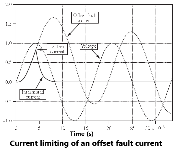
This limits the current, but it also improves the power factor, making the current more in phase with the voltage. Figure shows a fault current that is completely offset, in which case the magnitude is very high and the first current zero is delayed. The current-limiting fuse, however, causes the current to fall to zero as the voltage goes to zero, thereby limiting the maximum current to an amount called the “let-through current.”
There are three basic types of current limiting fuses . The first type is the backup current-limiting fuse. This fuse is very effective at high fault currents, but is not able to interrupt low currents; hence it must always be used with a conventional overcurrent device that will react to lower fault currents. The second type is the general purpose current-limiting fuse that, according to ANSI standard, is a current-limiting fuse that can interrupt a current that causes the fuse to operate in one hour or less. The third type is a full range fuse, which is designed to interrupt any current that causes its fusible element to melt under normal fusing conditions.
The best way to show the effectiveness of the current-limiting fuse is by computing the so-called I2t factor, which is the current time integral. This factor represents the heating that can occur per increment of resistance. Therefore, it is proportional to the allowable energy in the circuit. There are two parts of the I2t factor. The first part is the melting I2t, which can be determined by calculation. The second part of the I2t factor is that which occurs after arcing begins and continues until full current interruption occurs. This part must be determined by test.
The first requirement of any fuse is to extinguish the arc. The second requirement is that the cutout must be able to withstand the normal full rated voltage across the open fuse link. This usually involves a high frequency transient that rapidly damps out, followed by the normal power frequency voltage, which will be applied across the open cutout. The third requirement of the fuse design is that it must be capable of being coordinated with other fuses or other devices, so that the outage caused by the fault is restricted to the minimum protective zone.
Special Fuses
As noted earlier, special fuses are available to satisfy a variety of different system conditions. A few of these are described in the following text.
One application that sometimes requires special treatment is the fusing of capacitor banks. In some installations, changes in the supply system may cause the available fault current to increase, requiring a change in the capacitor bank fuses. In some cases, it may not be possible to change from a fuse to a more expensive circuit breaker because of space limitations in the existing installation, even though a circuit breaker could be selected with more than adequate interrupting rating.
One solution that has been developed for such an application is a special type of current-limiting fuse that has an unusually large interrupting rating . Capacitor bank fusing is also complicated by having a high-frequency inrush current when the bank is energized, which may cause problems in the fuse application.
Another problem situation sometimes encountered is that of the continuous current rating of the fuse for a given application. For satisfactory service, the fuse must have the correct voltage rating, full load current rating, and be able to sustain repeated overloads. In most cases, it is not recommended that fuses be placed in parallel in order to increase current rating, as there is no assurance that the two parallel fuses will melt and clear the circuit at exactly the same time, whether of current-limiting or zero current clearing types.
Special parallel fuse cutouts have been developed and are approved for application where increased current ratings are required. It must be emphasized that this is a special fusing device that is designed for this purpose and has been tested and approved for parallel current interruption. Paralleling common fuse cutouts is not recommended.
Another special type of fuse is the “electronic fuse”. This fuse uses integrated electronic circuitry to provide current sensing, the TCC, and the control of the fuse performance. The advantage of this fuse is that the TCC can be provided in several different types, making it possible to select the characteristic that best fits a particular application.
The fuse design includes a control module that uses a current transformer for current sensing, for input power to the electronic circuits, and to provide energy to operate the interrupting module. The control module also provides the TCC that controls circuit interruption. The interrupting module is controlled by the control module to provide current interruption. This is accomplished by signaling a gas-generating power cartridge to move an insulating piston, thereby shunting the fault current to fusible elements. After fault clearing, the interrupting module is replaced.
The special fuses mentioned here are examples of the ingenuity of fuse manufacturers in developing new fuses to meet the varied needs of the protection engineer. The descriptions are by no means complete, and the engineer should consult the manufacturers and suppliers for fuses that may be required for special system protection applications.
Voltage Ratings
Fuses are rated for applications in distribution and power systems over selected voltage ratings. Standardized voltage ratings have been evolving as harmonization efforts between North American and European Standards continue. Voltage ratings for different applications are not necessarily the same as each other. Two main application classes are described in. Class A (distribution class) and Class B (power class).